Map Materials to Individual Mesh Faces
This method is only available when creating a mesh using the MeshBuilder method.
The following meshes have identifiable faces: box; cylinder; extruded polygon and polyhedron have identifiable faces and have the faceUV and faceColors parameters in the options using the MeshBuilder method to create them. This means that each of their faces can have a different texture or color. For colors a particular color is mapped to a particular face. For textures part of the image file is mapped to a particular face. This can be done with any image and it is often useful to use a texture atlas containing a number of images combined into one image file.
When you are concerned about the orientation of the images on the faces then it can be necessary to have different orientations of the separate images in the image file.
Using these methods on the above meshes there is no need for submaterials or submeshes.
As a prerequisite, you may want to learn more about UV mapping on Wikipedia.
Face Numbers
The playground below shows that face numbering using MeshBuilder.CreateBox is that
- side 0 faces the positive z direction
- side 1 faces the negative z direction
- side 2 faces the positive x direction
- side 3 faces the negative x direction
- side 4 faces the positive y direction
- side 5 faces the negative y direction
Texture Atlas
A texture atlas also known as a sprite sheet or sprite atlas contains a range of images as in the example below.
In this atlas there are 24 different images in 4 rows of 6. Each sprite image is mapped onto a face using uv coordinates. The u coordinate goes horizontally left to right from 0 to 1 and the v coordinate goes vertically bottom to top from 0 to 1.
To map part of the image the bottom left coordinates and top right coordinates are used. Using (0, 0) and (1, 1) will use the whole of the texture atlas. In this case there are six sprites in a row and four in a column divide the image into a grid and mark the axes as below
Consider the sprite in the grid space marked with a *. Counting the columns as 0, 1, 2, 3, 4, 5 and the rows as 0, 1, 2, 3 it is in column 2 and row 1 and so bottom left is (2 * 1/6, 1 * 1/4) = (2/6, 1/4) and top right is ((2 + 1) * 1/6, (1 + 1) * 1/4) = (3/6, 2/4).
In general for this texture atlas a sprite in column c and row r will have coordinates bottom left (c * 1/6, r * 1/4) and top right ((c + 1) * 1/6, (r + 1) * 1/4). With faces of the mesh numbered from 0 when you want to map face f to the sprite at grid (c, r) take an array faceUV and put
faceUV[f] = (c * 1/6, r * 1/4, (c + 1) * 1/6, (r + 1) * 1/4);Assigning the texture atlas as a texture material to the mesh is done as usual
var mat = new BABYLON.StandardMaterial("mat", scene);var texture = new BABYLON.Texture("URL of Texture Atlas", scene);mat.diffuseTexture = texture;
mesh.material = mat;
Colors
To apply a color to a face f just use an array faceColors and assign a color.
faceColors[f] = new BABYLON.Color4(r,g,b,a);For colors only no material is needed.
These colors are BJS Color4-class values. The Color4 alpha values become active if we set hasVertexAlpha = true :
Combine Colors and Textures
You can even combine the vertex colors with a colored material.
faceUV[f] = (c * 1/6, r * 1/4, (c + 1) * 1/6, (r + 1) * 1/4);faceColors[f] = new BABYLON.Color4(r,g,b,a);Examples of Per Face Material
The box example demonstrates the full scope of this feature. At least one example is provided for each of the other types of mesh that can use faceUV and facecolors
Box - faceUV
A box has six faces so only the bottom row, row 0, of the texture atlas above is used on the box in these examples.
To map sprites 0 to 5 onto faces 0 to 5 it is sufficient for the face number to match the column number and to set the row number to 0.
var columns =  6;  // 6 columns  var rows =  4;  // 4 rows
  var faceUV = new Array(6);
  for (var i = 0; i < 6; i++) {    faceUV[i] = new BABYLON.Vector4(i/columns, 0, (i+1)/columns, 1/rows);  }
Then this array is passed to the faceUV option to be used in the MeshBuilder.CreateBox() method along with any options for the size of the box and the material formed with the given texture atlas.
var options = {   width: 10,   height: 3,   depth: 5,   faceUV: faceUV};
var box = BABYLON.MeshBuilder.CreateBox('box', options, scene);
var mat = new BABYLON.StandardMaterial("mat", scene);var texture = new BABYLON.Texture("URL of Texture Atlas", scene);mat.diffuseTexture = texture;box.material = mat;You do not have to map all the faces. When you just want one face with an image then just map that one face.
Take the alien sprite on row 0 and column 3 and just map this sprite to face 1.
var columns =  6;  // 6 columns  var rows =  4;  // 4 rows
  var faceUV = new Array(6);
faceUV[1] = new BABYLON.Vector4(3/columns, 0, (3+1)/columns, 1/rows);As you view the box in the above playground from different angles you will notice that the whole texture atlas is applied to all the other faces, that is the default value (0, 0, 1, 1). When you want to display just the one sprite on the one face and leave the others blank then you need to set all the other faceUV values to (0, 0, 0, 0).
var columns =  6;  // 6 columns  var rows =  4;  // 4 rows
  var faceUV = new Array(6);
  //set all values to zero  for (var i = 0; i < 6; i++) {    faceUV[i] = new BABYLON.Vector4(0, 0, 0, 0);  }
//overwrite wanted face with sprite coordinates faceUV[1] = new BABYLON.Vector4(3/columns, 0, (3+1)/columns, 1/rows);Of course you can do this with one, two, three, four, or five the box faces.
Want add some all over color to the box then just add in a_diffuseColor_ to your material.
Sprite on Box Face With Material ColorYou can also use one texture atlas to apply two different images from the same sheet onto two different meshes.
Sprites Sheet On Faces of 2 MeshesLooking closer at the face images around the sides you will see some images are at 90 degrees to others. Unfortunately should you want to have all images around the side to have the same orientation this is not possible by only adjusting UV coordinates. What can be done by swapping coordinates is considered next, followed by a method using an adjustment to the texture atlas to orientate images on the sides.
How To Orientate a Sprite on a Face with faceUV
Because of how UV coordinates are interpreted it is possible to reflect a sprite horizontally, vertically or both (which is the same as an 180 degree rotation). Any other rotation has to be dealt with by rotating the sprite within the texture atlas.
Consider the alien with bottom left and top right coordinates for UV as shown.

To set this to face one in its current orientation you would use
faceUV[1] = new BABYLON.Vector4(Ubottom_left, Vbottom_left, Utop_right, Vtop_right);To reflect in a vertical line swap the horizontal, U, coordinates.
faceUV[1] = new BABYLON.Vector4(Utop_right, Vbottom_left, Ubottom_left, Vtop_right);To reflect in a horizontal line swap the vertical, V, coordinates.
faceUV[1] = new BABYLON.Vector4(Ubottom_left, Vtop_right, Utop_right, Vbottom_left);To reflect in both horizontal and vertical lanes swap the U coordinates and also swap the V coordinates.
faceUV = new BABYLON.Vector4(Utop_right, Vtop_right, Ubottom_left, Vbottom_left);You can use the images on the other faces in the following playground to check the change on orientation of the alien sprite in all the reflections.
Understanding Face Orientation With SpritesSince a Vector4 has the properties x, y, z, w, (in that order) setting
faceUV[1] = new BABYLON.Vector4(Ubottom_left, Vbottom_left, Utop_right, Vtop_right);means
faceUV[1].x = Ubottom_left;faceUV[1].y = Vbottom_left;faceUV[1].z = Utop_right;faceUV[1].w = Vtop_right;which gives another way to swap coordinates. For example to reflect in a vertical line do
var temp = faceUV[1].x; faceUV[f].x = faceUV[f].z; faceUV[f].z = temp;How To Orientate a Sprite on a Face with the Texture Atlas From Version 4.0
Three new optional parameters were added to CreateBox in the V4.0 update, these are
- wrap - boolean (default = false), when true all vertical sides (0, 1, 2, 3) will apply image textures in the correct, upright, direction and the two horizontal sides (4, 5) will apply image textures so that when the box is when rotated around the x axis so that these sides are vertical the applied image textures will be applied in their original orientations;
- topBaseAt - integer, 0, 1, 2, 3, (default = 1), the bottom (base) of the image for the top of the box is next the the side with the number given;
- bottomBaseAt- integer, 0, 1, 2, 3, (default = 0), the bottom (base) of the image for the bottom of the box is next the the side with the number given.
In the following playground the two boxes at the top do not use the wrap parameter and the result is backwards compatible with earlier versions of Babylon.js. The lower boxes are with wrap set to true.
Wrap Sprite OrientationThe next playground shows the use of non-default values for topBaseAt and bottomBaseAt
Wrap Top and Bottom Rotate Wrap Cartoon HeadHow To Orientate a Sprite on a Face with the Texture Atlas Before Version 4.0
Here consider just the orientation of the sides as viewed in the playground below.
Take the following texture atlas
and apply it to a cube to give the playground below
Default Image RotationLooking at the playground tells you two things
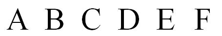
- Which face is number 0, which is number 1 and so on by matching letter to number
- Going round the sides the orientations vary by 90 degrees.
As you saw in the previous section it is possible to doubly reflect A so it is the right way up. It is not possible to do this with C and D. To have A, B, C, and D all the same way up the texture atlas itself has to be changed.
A is rotated 180 degrees and C and D are rotated 90 degrees counter clockwise. Taking this into account change the texture atlas to

resulting in the following playground
Aligning Images on FacesBox - faceColors
For this no material is needed.
Define a 6 element array faceColors (6 box faces) and just set the color of the faces we want with Colors4.
var faceColors = new Array(6);
  faceColors[4] = new BABYLON.Color4(1,0,0,1);   // red top  faceColors[1] = new BABYLON.Color4(0,1,0,1);   // green front
Then pass this array to the MeshBuilder.CreateBox() method with the new faceColors parameter of options.
var options = {    width: 10,    height: 3,    depth: 5,    faceColors : faceColors  };
var box = BABYLON.MeshBuilder.CreateBox('box', options, scene);These colors are BJS Color4-class values. The Color4 alpha values become active if you set hasVertexAlpha = true for the box.
Box - Mix Face Textures and Colors
Finally you can also mix per-face colors with per-face textures, and/or mix either with the material's standard colors.
Mixed Textures and Colors Per FaceCylinder
A cylinder has three surfaces, the top, the bottom and the tube joining them. For the face options face 0 is the bottom, face 1 is the tube and face 2 the top.
The following texture image is split into two parts, an approximation to a top and the label. The bottom will be colored just using faceColors and so the bottom face uv coordinates will be 0, 0, 0, 0.
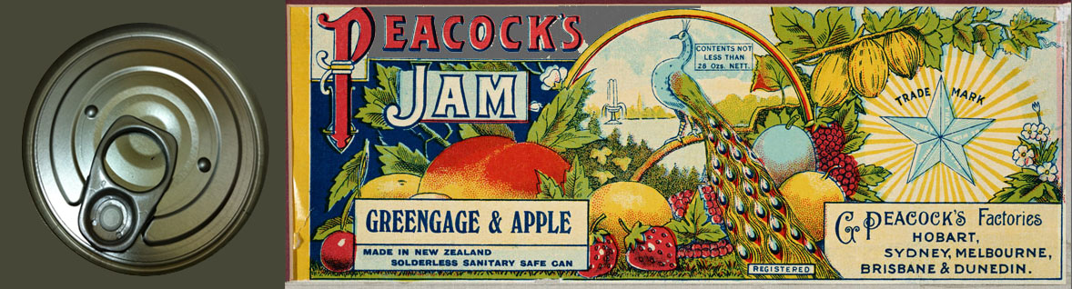
The label part has width 866 pixels and height 319 pixels.
So you need to tube surface to have the same height to width ratio.
When you create a cylinder with default diameter of 1 then the rectangle wrapping around the tube surface will have a width of π.
Letting h be the height of the cylinder then to not distort the aspect ration of the image wrapped around the cyclinder keep the ratios h/π and 319/866 the same.
So make h = π * 319/866 = 1.16 to 2 decimal places.
Also note that because of how a cylinder's mesh is constructed the horizontal coordinates (U) are swapped in faceUV[1] for the wrapped around image to correct the reflection of the image.
Different Texture on Cylinder and Its TopExtruded Polygon
An extruded polygon has three surfaces top, bottom and extruded sides, face 0 is the top, face 1 the extruded sides and face 2 the bottom.
Extruded Polygon with Different Textures on Sides and TopPolyhedra
You can use a texture atlas with all the polyhedra however without very careful consideration of the nature of the texture atlas the results can be a little random looking.
Polyhedra with Different Characters Per FaceHaving each sprite as a texture rather than a picture makes more sense.
Polyhedra with Different Textures Per FaceJust colors works well.
Polyhedra with Different Colors Per Face